
In this third part of my essay on successful development of vision machines, I will discuss the need for research, prototypes and mock-ups prior to building the customer’s machine.
Occasionally, the machine vision integrator may have had experience in applications which are similar to the one at hand and can make a reasonable estimate of how to design the current machine. Other times, the current application may encompass a significantly novel feature, such as some peculiarity about material handling, the product surface characteristics, contamination or throughput volume requirements. The purpose of research is to understand enough of the prospective solution either to be able to make a quote or to decide that it is not feasible. Research at this point should be relatively simple, for time and cost reasons.
The first two examples presented exhibit research to determine is sufficient clarity of view is available for reliable defect imaging.
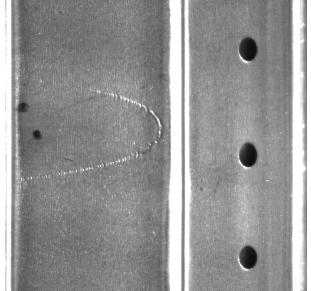
In the example number one, a cylindrical metal part has a surface blemish that is to be detected.
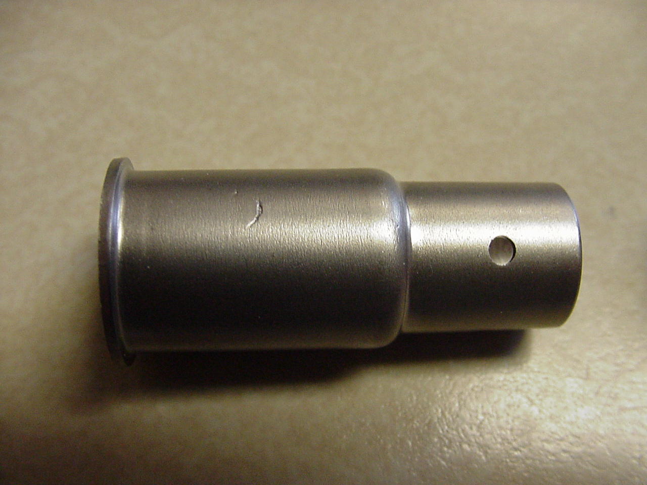
At one stage of production, the part is turned on a spindle.
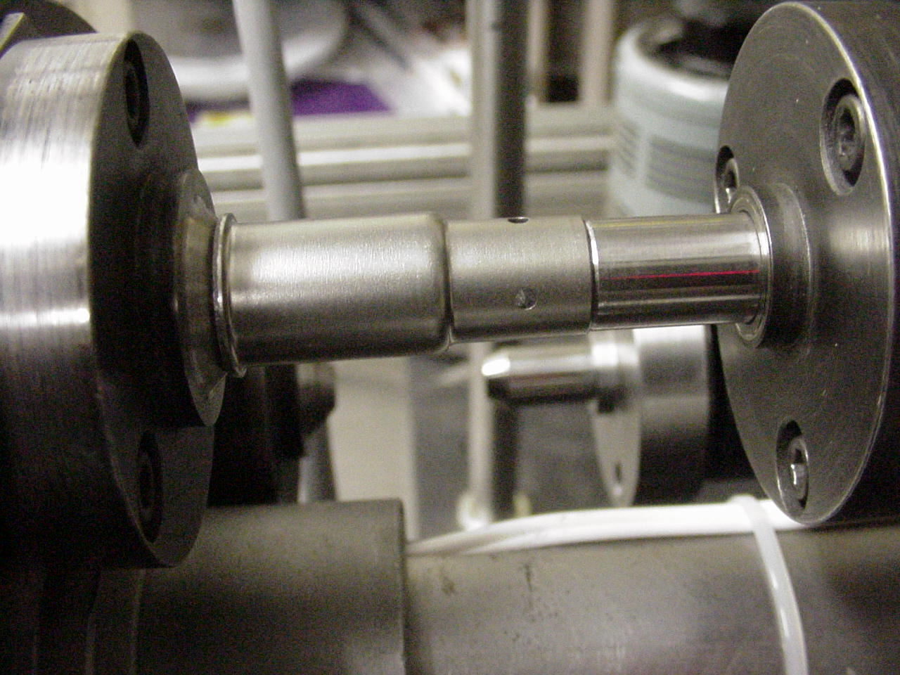
The research objective is to determine what camera and lighting configuration will allow this defect to be detected. A simple apparatus is set up to mimic the material handling at the point of access in the production line.
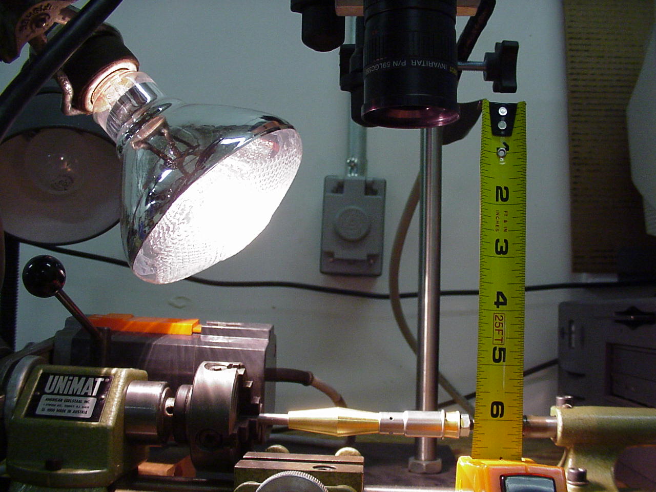
In this case, a line scan camera in conjunction with very specific lighting, is capable of reliably imaging the defect.
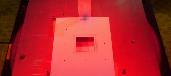
Another simple research example, this one involves a determination of whether the application offers sufficient clarity of access for imaging and illumination. In this case, the inspection required is of the under side of a product that is contained by and moved on a multiple-lane, high-speed conveyor.
First the basic imaging capability testing is done in the laboratory.
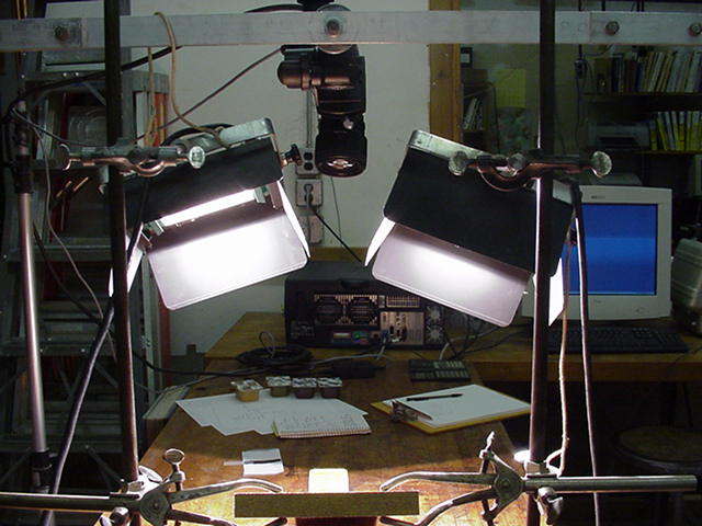
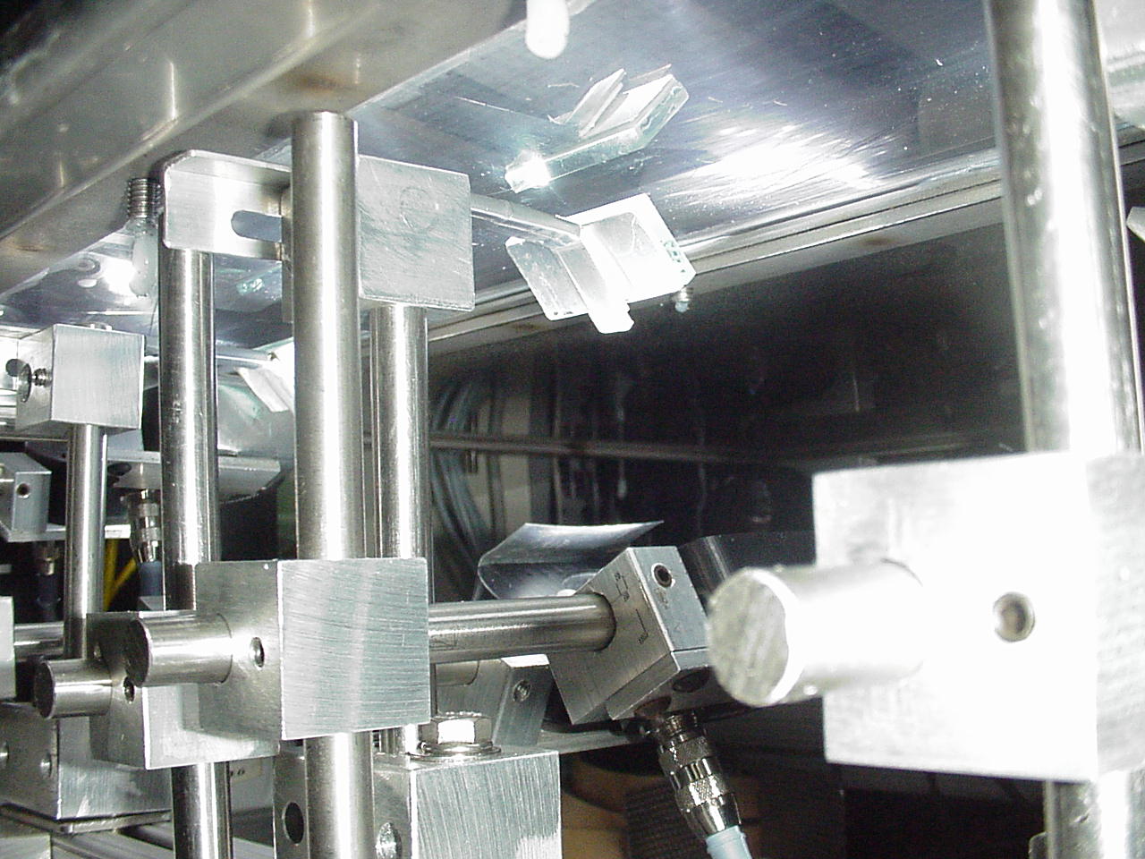
The first step is to make a geometrical model of the under side of the gap between the conveyors, through which the imaging will be done. This model is shown upside down and placed over a lab conveyor which is used to propel the product under the modeled gap. Line scan imaging and illumination are tested as the product is conveyed through the model.
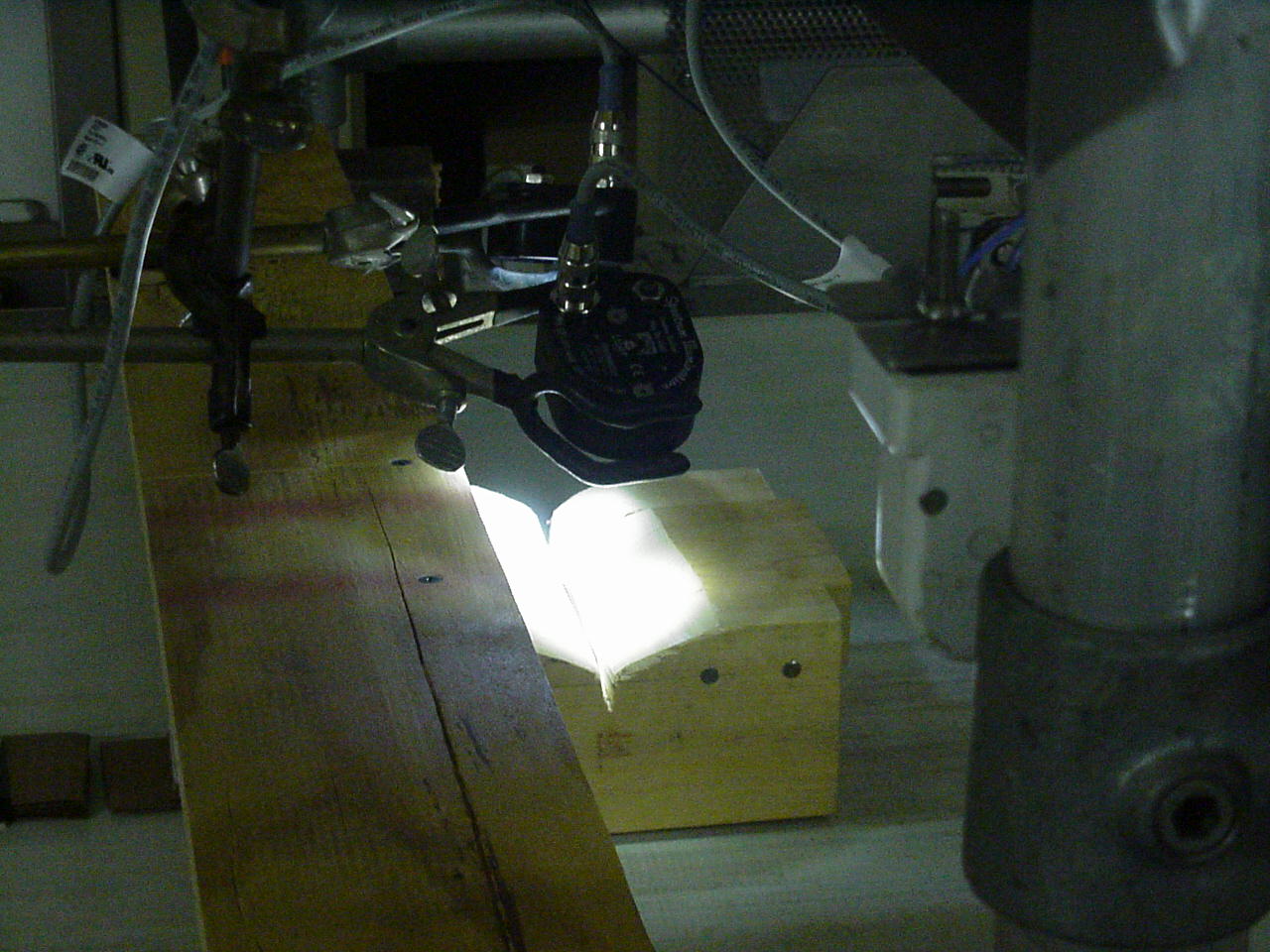
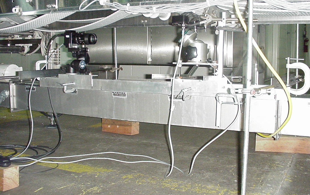
After the laboratory testing shows capability for imaging, the next step is to test imaging on the real production line, in the factory. In this case the setup includes a camera, LEDs and a mirror. The entire setup is mounted on a framework of bars and clamps for easy adjustment. All equipment is constrained to be located below the conveyor (to view the underside of the product) and above an existing cabling conduit. The access is quite physically limited.
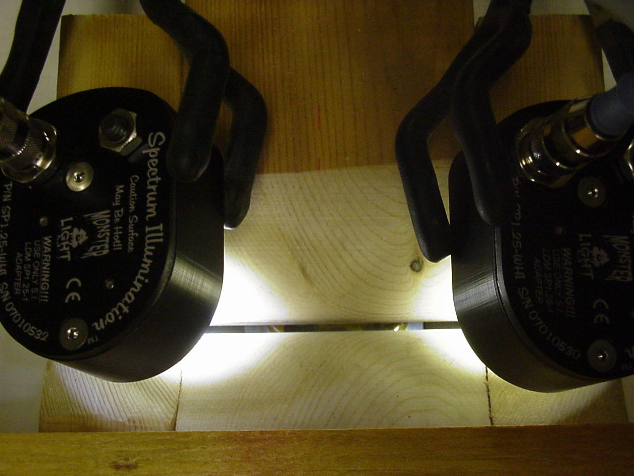
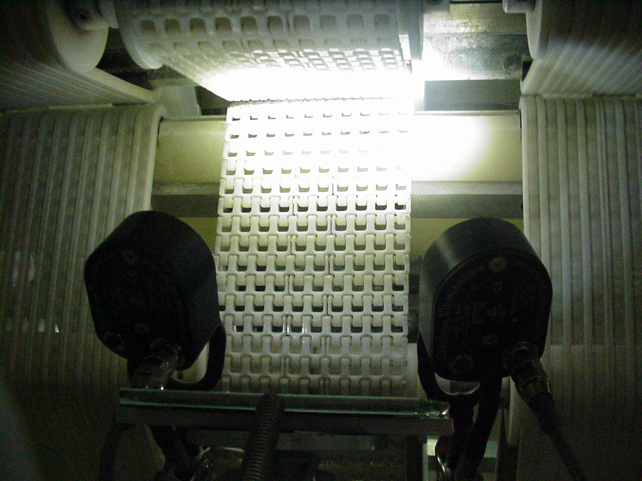
Here is a view of the real conveyor gap, through which the product is to be inspected. This view is from under the conveyor, looking up. A mirror used to direct the line of sight upward, is shown from a later stage of development.
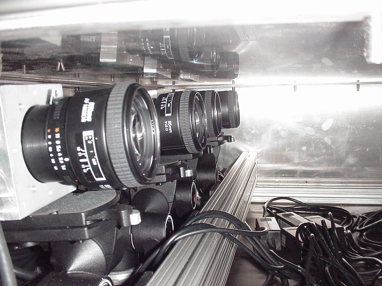
The developed vision machine meets the access constraints, placing cameras, LEDs and mirrors in an enclosed cabinet, under the conveyor and above the existing cabling conduit. Inside the cabinet are four cameras, one for each lane, each viewing through four mirrors which direct the line of sight vertically upward, through the conveyor gaps. Illumination is provided by eight high-intensity LEDs.

The next set of examples relate to cleanliness and countering contamination which interferes with imaging.
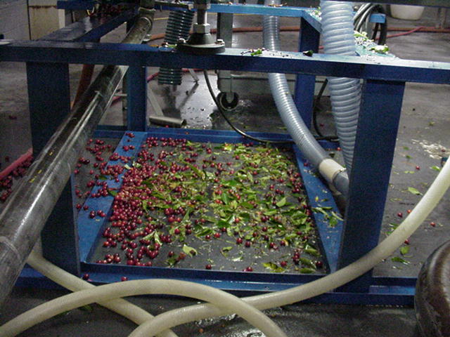
Some kinds of products in the real manufacturing environment, when being automatically handled, will shed particulates that can obscure the line of sight of the vision system.

This requires a means of keeping the line of sight clear. In this instance, a low-profile air manifold, providing constant, low volume air flow, does the job.

High-speed food processing also inherently scatters some product. Periodically, personnel wash-down the equipment, but a means of constantly keeping the vision equipment clean is required.
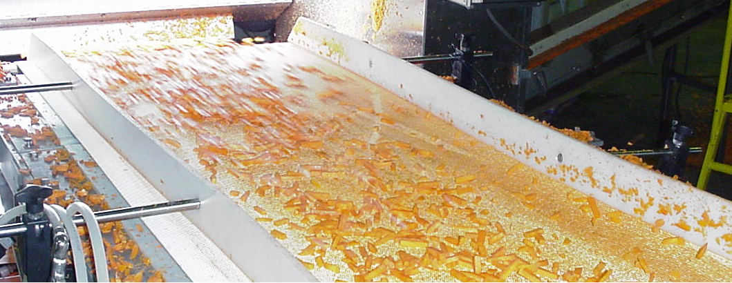
Here, a high-velocity fan drives a constant flow of clean air over the camera window, keeping it free of debris.
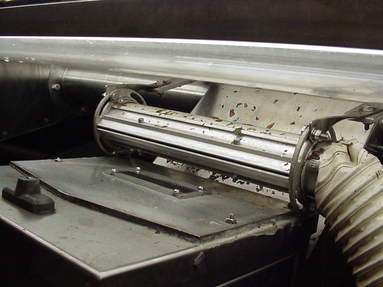
Sticky materials (apple pieces) are removed mechanically here with a wiper, water spray and an air jet.

The third critical factor to successful machine vision, consistency, is exhibited in the following examples.
One mode of using on-belt line scan imaging is to image through a small gap between two conveyors, positioned nose to tail. The above discussion about locating cameras beneath the conveyor and redirecting the line of sight upward, using mirrors, gives an example of this. Another example uses backlighting, with the back light positioned below the conveyors, illuminating the gap. In both situations, the product is being imaged as it spans the gap between the conveyors. This presents a challenge to maintain consistent, smooth transition between the conveyors. This can be done in high-speed applications by designing a mechanism to dynamically bear on the top of the product and drive and govern its passage across the gap. In low-speed applications, the product may not be so prone to “hopping” and careful alignment of the heights of the conveyors may suffice to give a smooth transition.
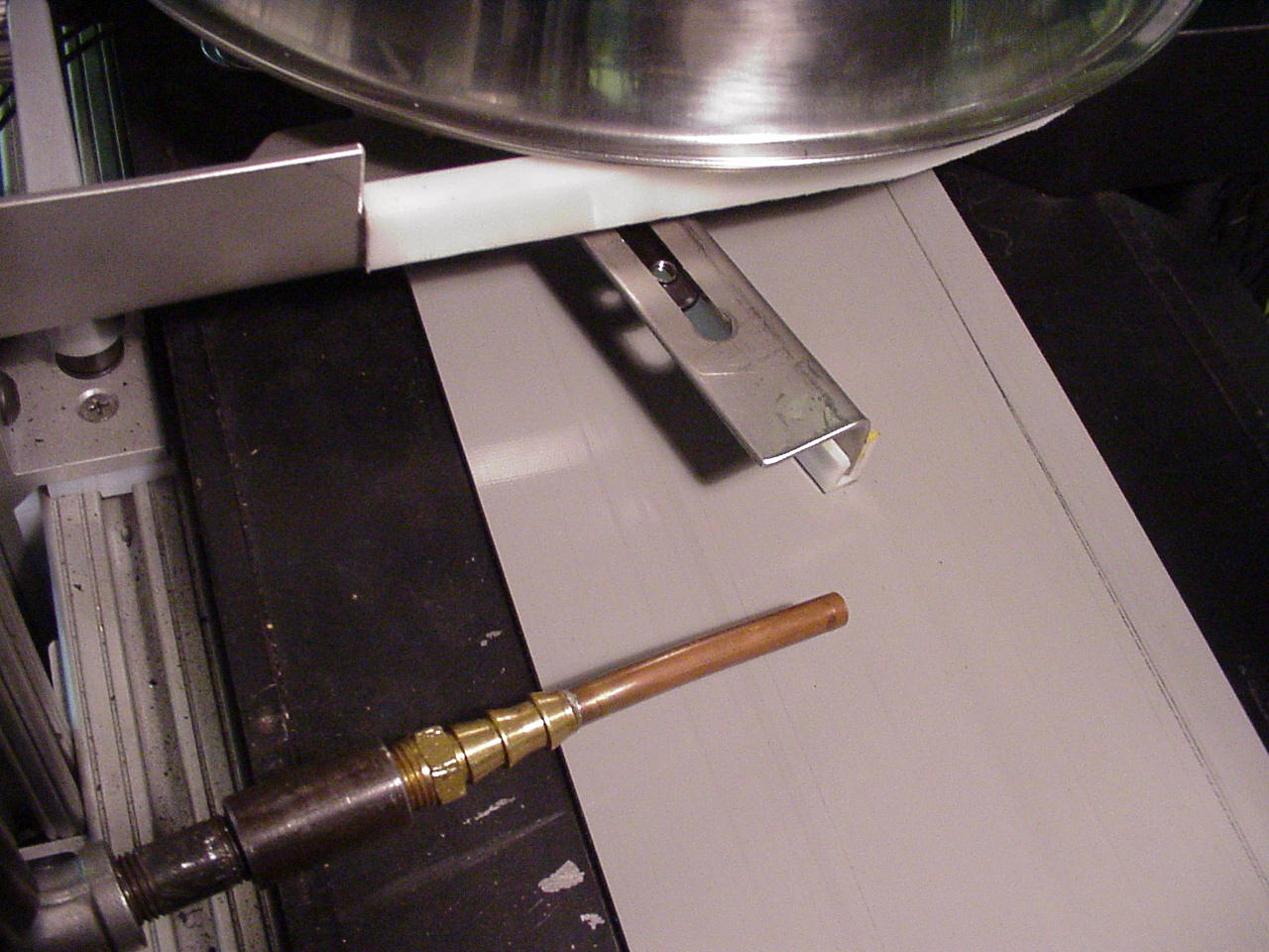
Industrially, a vision machine usually is used for inspection and needs to remove non-conforming parts. Here, as well, the material handling properties of the product may have a bearing on the consistency of the machine’s operation. In this example, after imaging and prior to air-ejection, a guide is used to positively force the product over a release slot formed in the conveyor. This ensures release of the rubber, suction cup-like product, from the belt.
As a final example for discussion, simple laboratory methods are sometimes used after a machine is built, to understand and correct aberrant behavior. Sometimes the operation of high-speed machines is difficult to perceive, and therefore difficult to adjust, without diagnostic instrumentation. For example, triggered imaging can be used to stop action and reveal the details of rapidly occurring processes.
This looks OK, except for the fact that the part was supposed to be ejected. Triggered imaging clearly showed what was happening and adjustment was then straightforward.